Chapter 5 Serial DMS
Physical Build Part 1
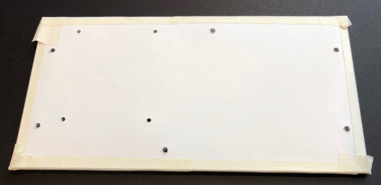
Lexan back plate
- Print off the back plate drill mask and cut it out with scissors or an X-ACTO knife and straightedge for a more accurate cut
Make sure when printing that the PDF is printed at exactly 100% size to ensure the drill mask is accurate. Some system print dialogs will want to automatically scale and size the image. The outer dimensions of the drill mask should be 190.5mm X 95.25mm when printed.
- Use the drill mask as a guide to score and snap an 8x10 Lexan sheet to size with a plastic scoring tool and a straightedge
You should only have to do this process twice - once for the long edge and a second time for the short edge, using the existing edges on the original Lexan sheet for the other two sides of the back plate.
- Tape the drill mask to the solid Lexan back plate as squarely as possible using masking tape
- Use a 3/32" drill bit on a Dremel press or drill press to make the Raspberry Pi mounting holes for the M2.5 machine screws in the back plate (4 smaller holes)
- Use a 7/64" drill bit to make the RGB LED matrix case mounting M3 machine screw holes (6 larger holes)
Keep the protective backing on both sides of the back plate until it is ready to install. Take your time when drilling and use a medium speed with very little pressure so as not to melt the Lexan.
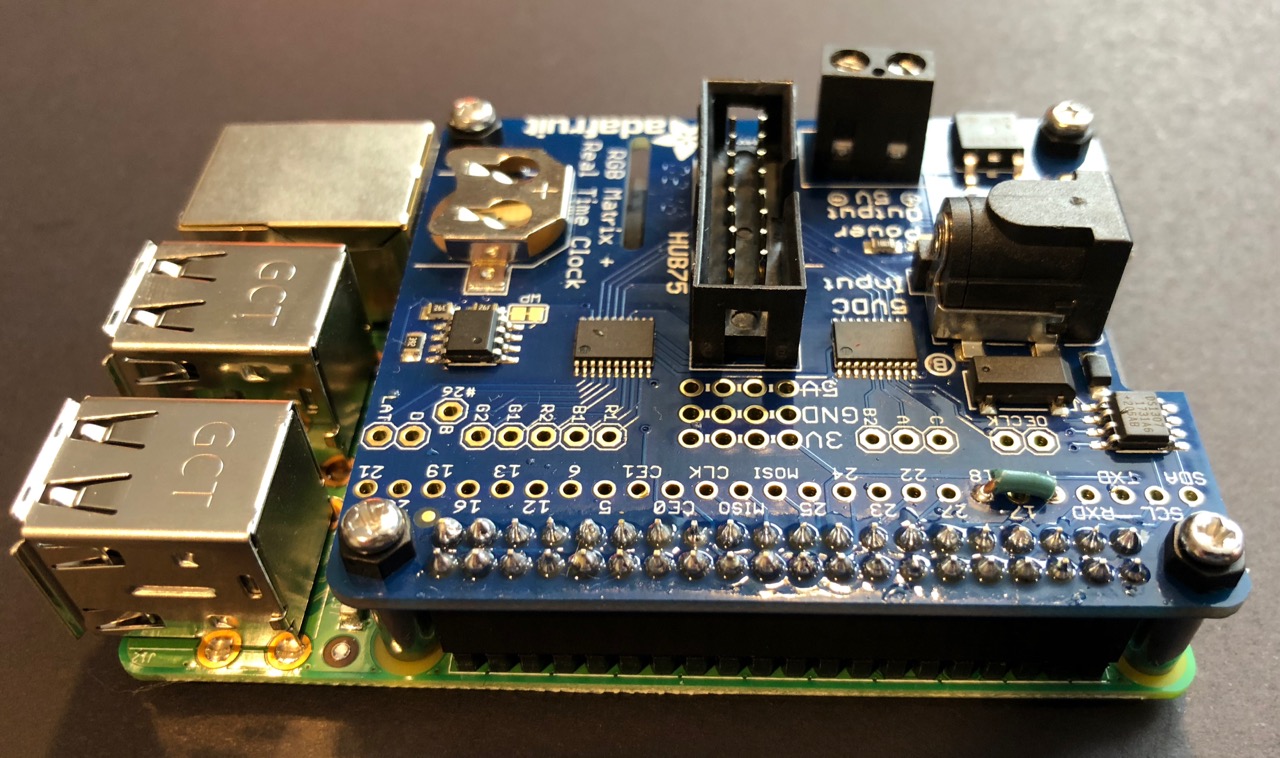
Raspberry Pi 3 and RGB LCD Matrix Hat
- Assemble the RGB LCD Matrix Hat using the instructions here:
https://learn.adafruit.com/adafruit-rgb-matrix-plus-real-time-clock-hat-for-raspberry-pi/assembly
- Solder a jumper wire from GPIO4 to GPIO18 on the Matrix Hat
- Mount the Matrix Hat to the Pi using (4) M2.5 11mm standoffs, (4) M2.5 nylon nuts, and (4) M2.5 screws to secure it in place
Software Setup
- Follow the instructions in the Chapter 3 Raspberry Pi Installation document to set up the Raspberry Pi with an initial environment and connect it to the IR829 Wi-Fi
- Log in as
piconvia SSH and install pip and pyserial
sudo apt update
sudo apt install python3-pip
sudo pip3 install pyserial
- Add root to the dialout group
sudo adduser root dialout
- Install the RGB LED matrix Python library
cd
curl -O https://raw.githubusercontent.com/adafruit/Raspberry-Pi-Installer-Scripts/master/rgb-matrix.sh
sudo bash rgb-matrix.sh
yto continue2for the Adafruit RGB Matrix HAT + RTCnto not install realtime clock support1to select theQualityoptionyto continue installation
The installation process will take around 5 minutes to complete.
- Enter
nto skip the reboot once installation is complete - Remove the RGB LED matrix installer
rm rgb-matrix.sh
sudo rm -rf rpi-rgb-led-matrix
- Install the dms-sim software
mkdir dms-sim
cd dms-sim
wget -O dms-sim-latest.zip -L 'https://cisco.box.com/shared/static/1g38uun7ojs6aoyxbox0l94c0h6twafw.zip'
unzip dms-sim-latest.zip
rm dms-sim-latest.zip
dms-sim.ini file:
- The font path if not using
piconas the user (not recommended) - The serial port path if not using
/dev/ttyUSB0 - The serial speed if not using
115200
Note that If you do change the font path because you aren’t using
piconas the user (again, this is not recommended), you will also need to change thedms-sim.servicefile.
- Set up the service and enable it on boot
sudo cp dms-sim.service /lib/systemd/system/
sudo systemctl enable dms-sim
- Power down the system to complete the physical build
sudo poweroff
Physical Build Part 2
Completing the Case
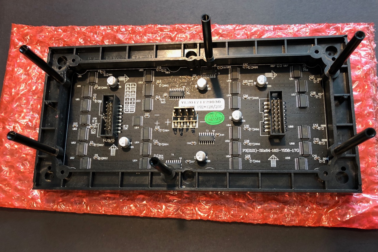
- Insert (6) 12mm M3 grub screws into the RGB LED matrix using the supplied hex wrench
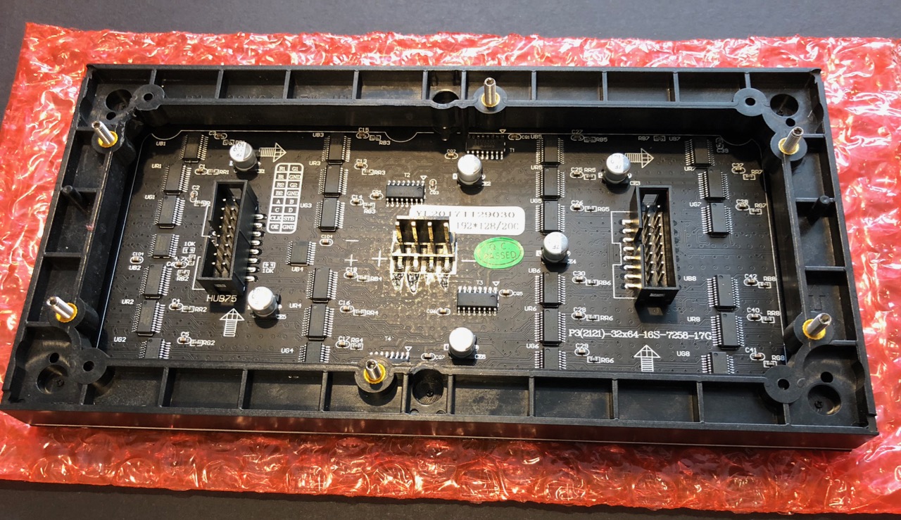
- Attach (6) 40mm M3 standoffs to the grub screws until they are flush with the plastic of the RGB LED matrix
- Take the drill mask, tape, and backing protective plastic off the drilled Lexan case back
Tip: Do this over a trash can unless you like small pieces of plastic on everything.
- Attach the following to the Lexan case back:
- (4) M2.5 screws
- (4) M2.5 washers
- (4) M2.5 nylon nuts
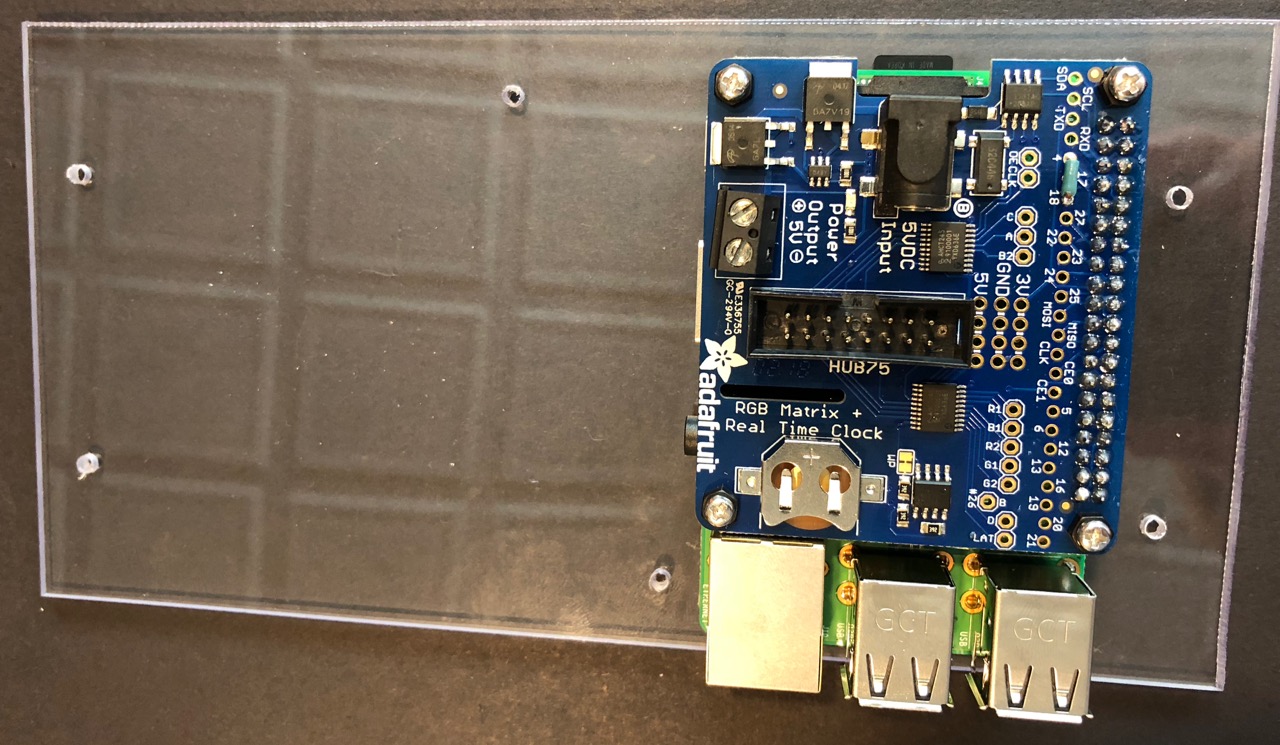
The screws and washers go on one side of the Lexan and the nylon nuts go on the other side. The nylon nuts act as spacers for the next step when the Pi is mounted to the Lexan. Make sure it matches the picture below.
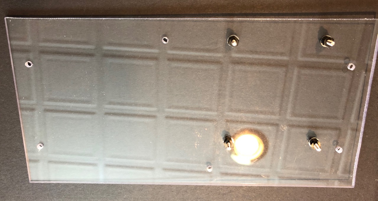
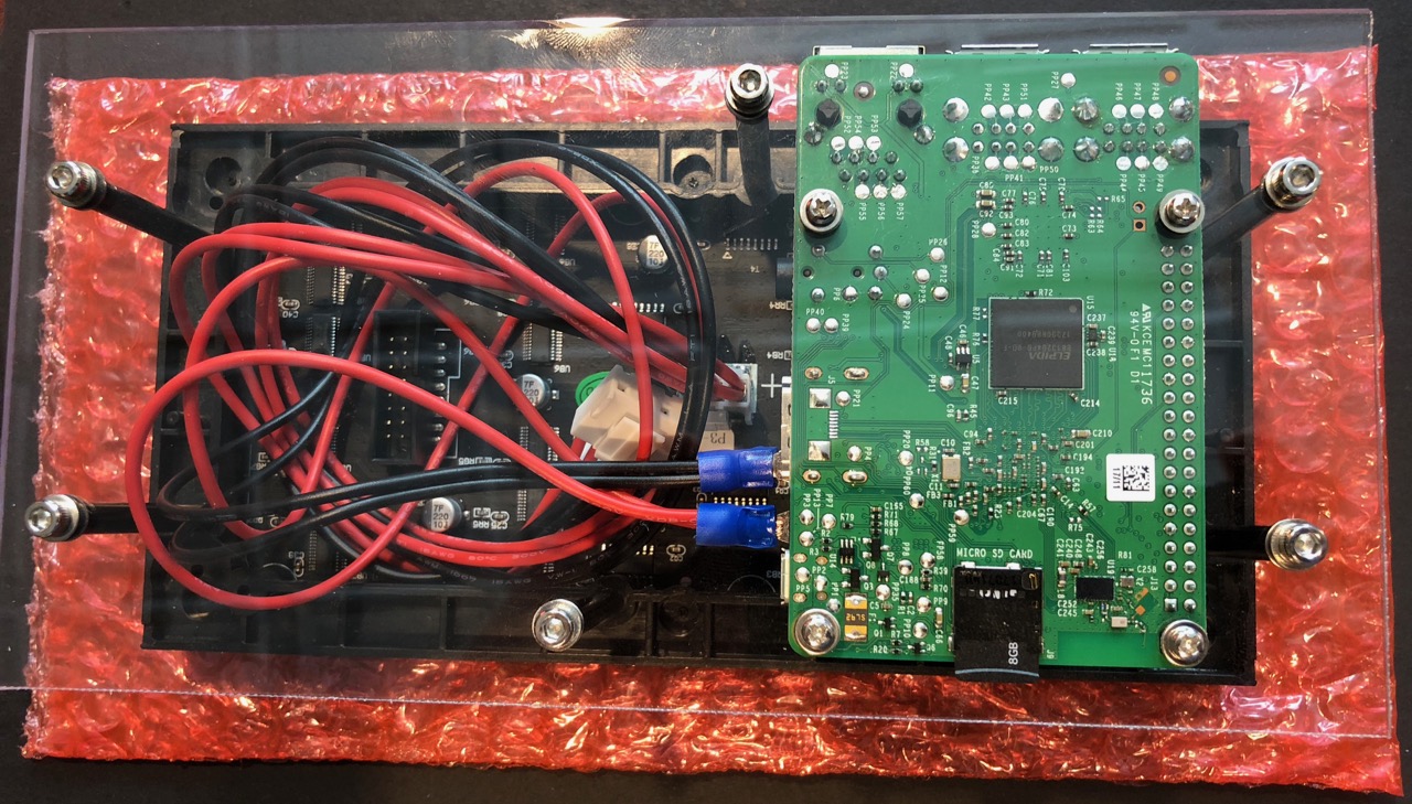
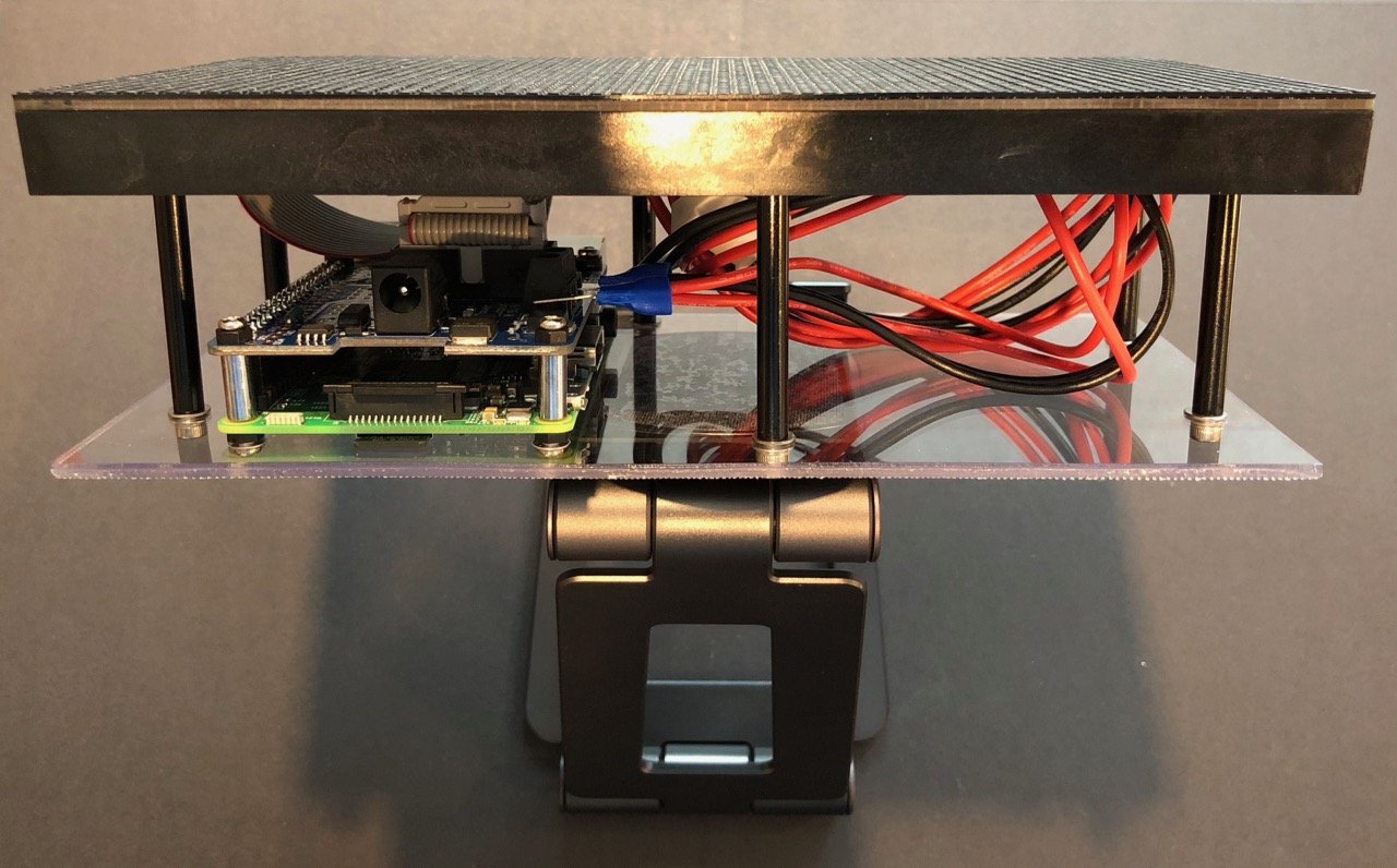
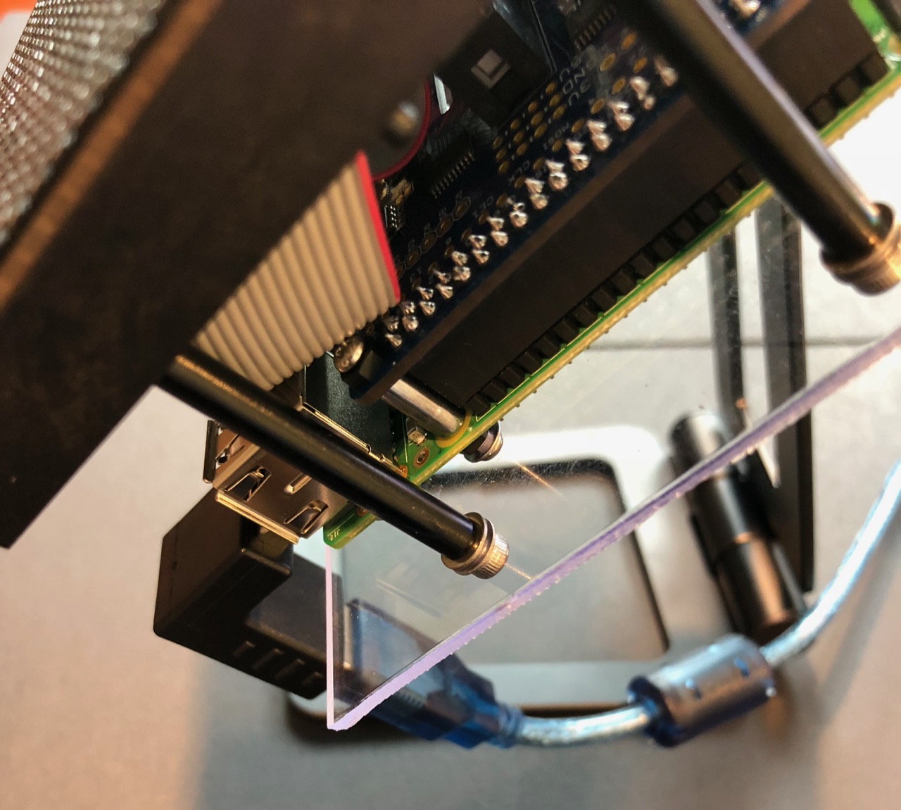
- Mount the Pi to the Lexan connecting the M2.5 screws that were just installed to the bottom of the M2.5 11mm standoffs separating the Pi and the RGB LED Matrix Hat. The SD card should be facing up and closest to the Lexan as in the picture below.
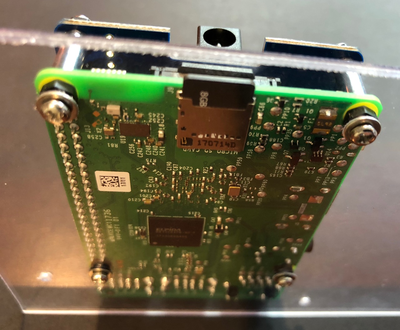
Here is a view from the other side showing how the pieces fit together.
- Connect the ribbon data cable from the RGB LED Matrix Hat to the RGB LED matrix. Make sure to connect to the input HUB75 connector based on the direction of the arrows, which point away from the input connector. The connectors are keyed.
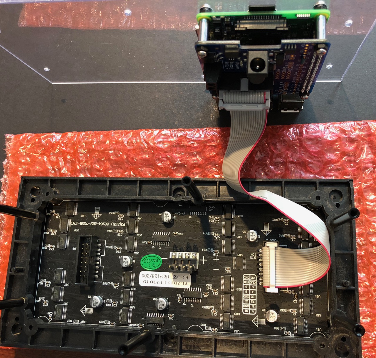
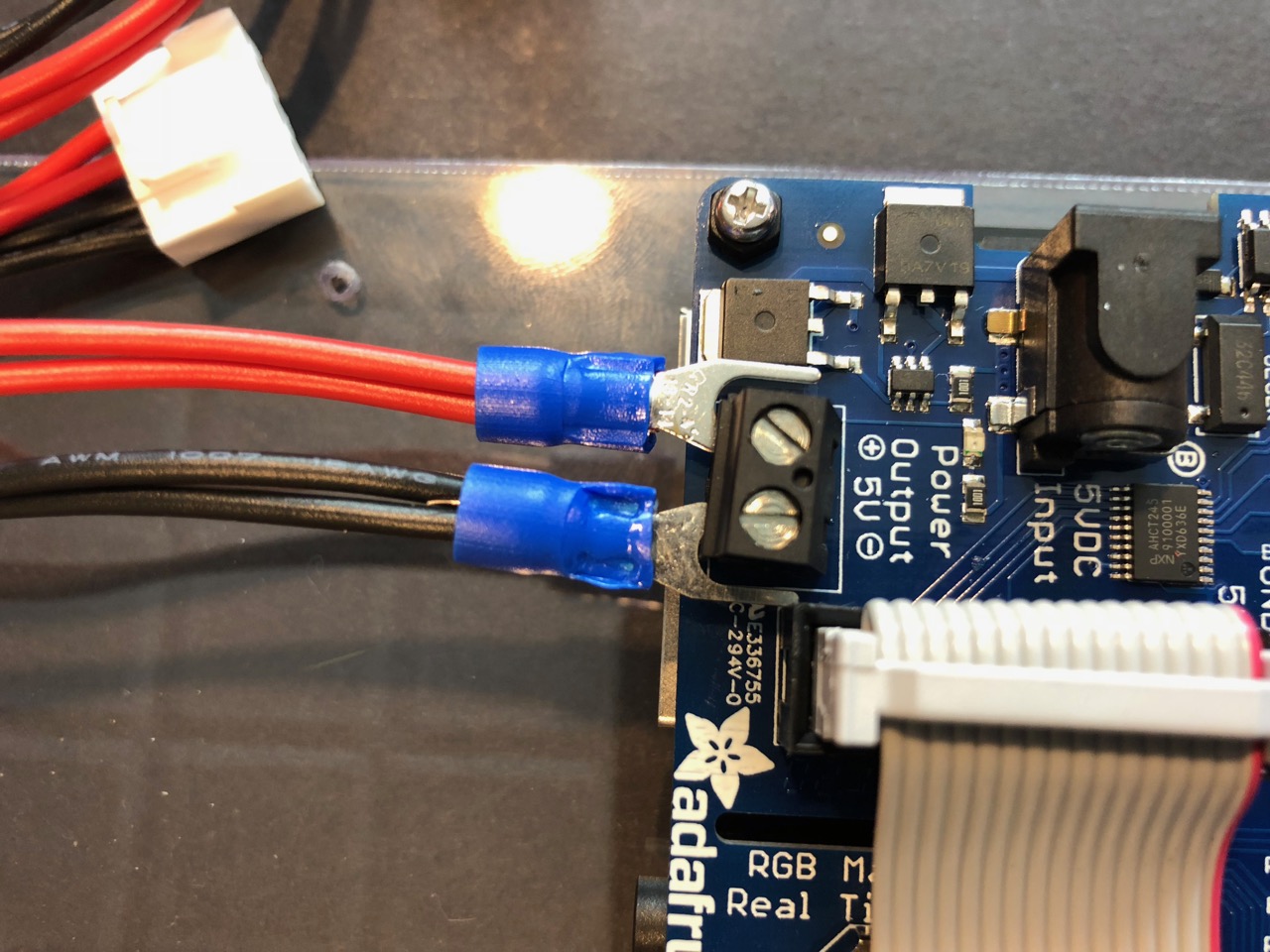
- Connect the spade ends of the power cable to the RGB LED Matrix Hat, making sure to secure the red-wired spade with the positive screw-down terminal and the black-wired spade with the negative screw-down terminal
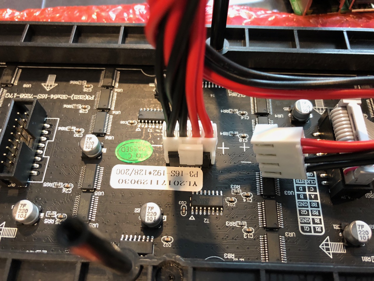
- Connect the plastic Molex end of the power cable to the RGB LED matrix power connector, again matching up the red-positive and black-negative connections
- Tuck the data and power cables between the Lexan and the RGB LED matrix
- Mount the Lexan on the ends of the 40mm M3 standoffs connected to the RGB LED matrix using:
- (6) M3 washers on the inside of the Lexan
- (6) M3 washers on the outside of the Lexan
- (6) M3 screws
You will likely need to use a 3/32 hex wrench to get some of the M3 screws started into the Lexan due to the tight fit, but after a few turns you should be able to complete the installation by hand. Small needle-nose pliers are helpful for holding the M3 washers in place on the inside of the Lexan while aligning the M3 screws to the 40mm M3 standoffs and screwing them in. Be careful not to over tighten the M3 screws.
Mounting the DMS
- Remove the adhesive backing on the large metal plate from the Scosche mounting kit and place the plate on the Lexan back case roughly in the center as shown below
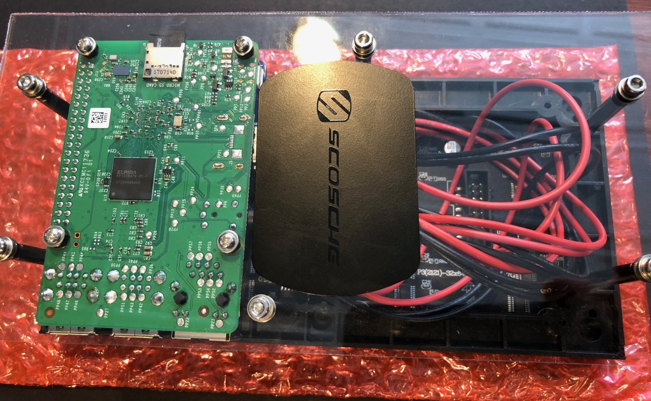
Press firmly on both sides of the Lexan plate to avoid pushing on just the top and accidentally cracking the Lexan.
- Use the included alcohol wipe to prep the soft rubber surface of the stand for the adhesive magnet mount, waiting until the alcohol has completely evaporated and the surface looks dry before moving to the next step
- Remove the backing from the adhesive magnet mount and place it on the stand as shown below, holding firm against the back for 30-60 seconds to ensure a good seal
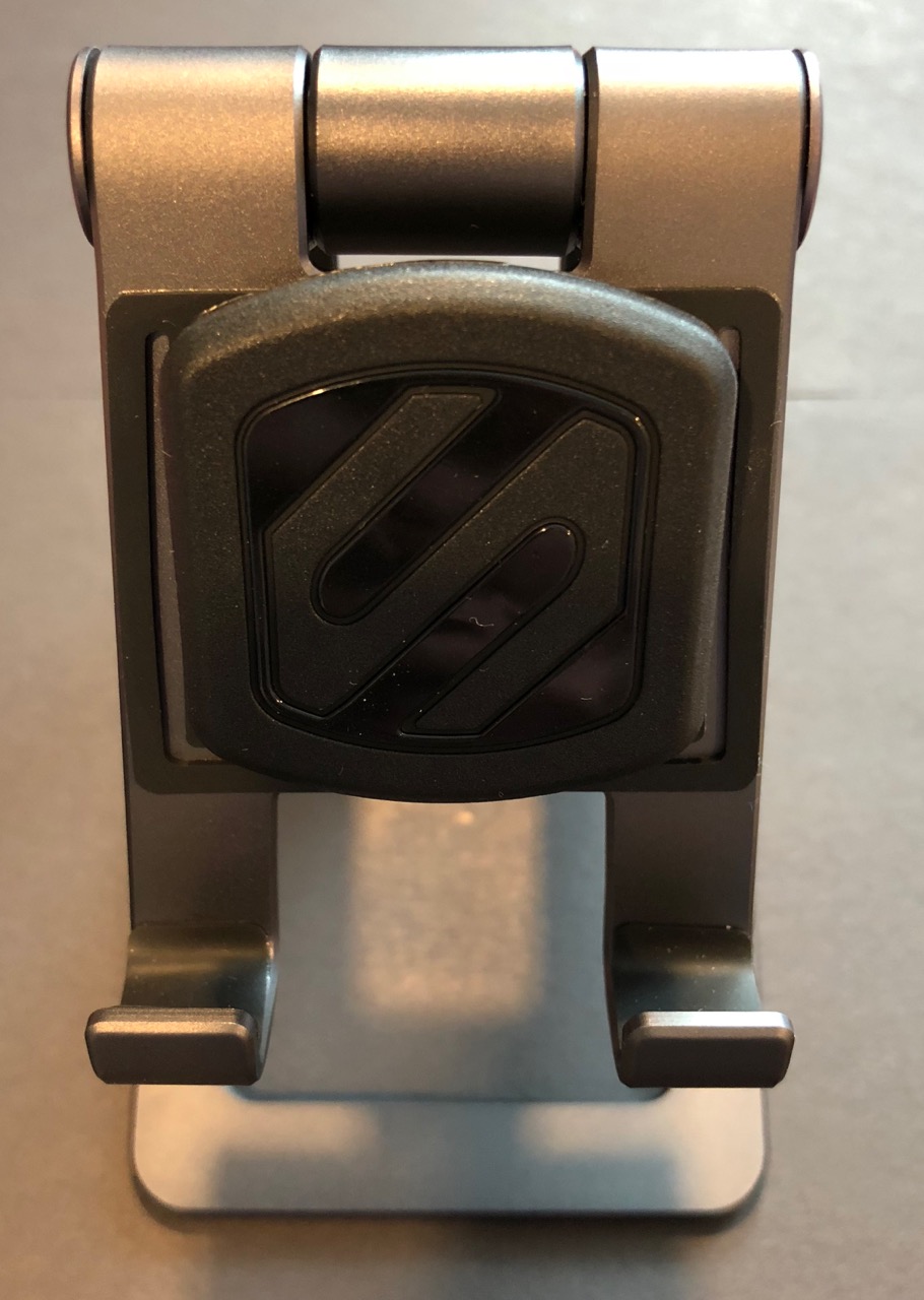
- The DMS can now be quickly secured on the stand for demos and easily removed for traveling and storage
Serial cable and connection to the IR829
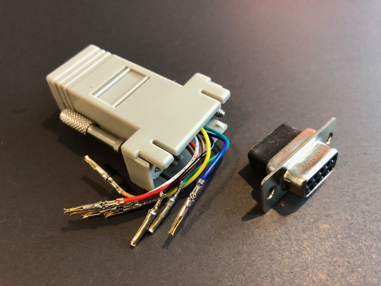
- Wire the DB9 female to RJ45 modular adapter using these pinouts:
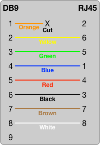
The DB9 connector from the recommended parts list has the pin numbers written on the front and back. The colors may be different if a different adapter is used. In that case, reference the RJ45 pin numbers to determine the correct colors.
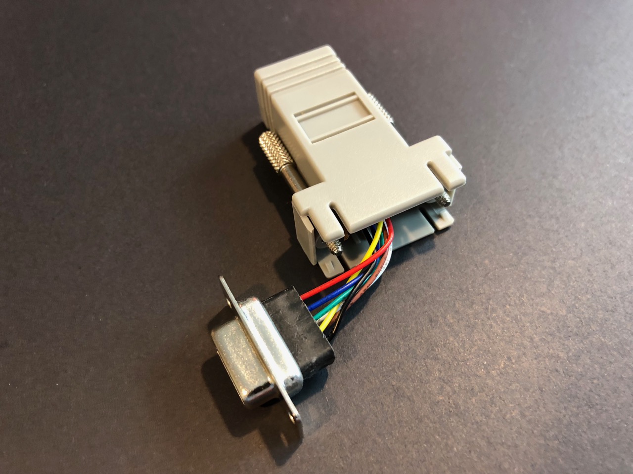
- Push the DB9 end into the top of the adapter until it clicks and is secure. The integrated screws should be able to turn freely and come out through the DB9 metal mounting plate.
- Connect the DB9 end of the adapter into the DB9 end of the USB serial cable
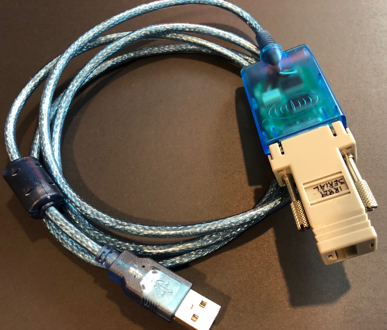
- Connect a standard Ethernet cable into the RJ45 end of the adapter and into the Serial 1 port of the IR829
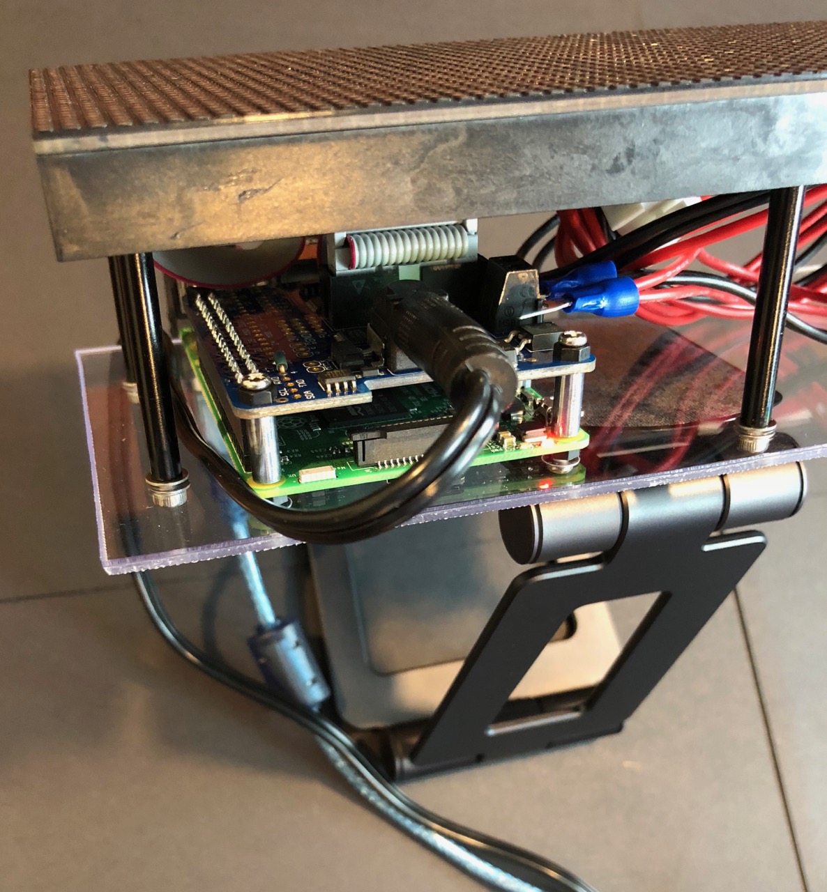
- Connect the USB end of the USB serial cable into the down-angle USB adapter
- Connect the down-angle USB adapter into one of the Raspberry Pi USB ports
Powering the DMS
- Run the DC power cable down the side of the Pi between the RGB LED matrix and the Lexan back so the cables to the DMS are aligned and easy to manage
Did It Work?
Yes!
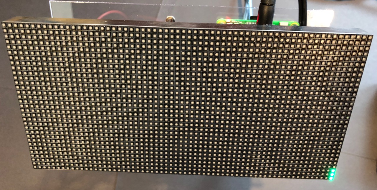
On boot the DMS will show 3 green lights in the lower right-hand if the USB serial adapter is connected and it is waiting for input. This is how you know the RGB LED matrix display and USB serial are all working correctly after the installation procedure.
If you have jumped ahead and configured the IR829 EFM broker to send serial messages you may even see a message like DRIVE SAFELY.
Ether way, well done!
Even if this was successful, it is worth browsing the troubleshooting steps below as you could still run into issues displaying serial message after configuring the IR829 EFM broker. Especially the step describing how to run
dms-sim.pyin debug mode.
No!
Here are some troubleshooting steps to consider:
- If the USB serial adapter is disconnected the RGB LED matrix will instead show 3 red lights in the lower right-hand. Connect the USB serial adapter and you should see the green lights in a few seconds.
- If the RGB LED matrix doesn’t show anything make sure you didn’t skip any installation steps and that power is connected into the barrel jack of the RGB Matrix Hat using the 4A 5V DC adapter.
The Pi itself should have a small red LED and the RGB Matrix Hat should have a small green LED when power is correctly applied. Both of these are easily visible when the DMS is viewed from the top.
- You can SSH into the Pi as
piconandsudo cat ~/dms-sim/dms-sim.logto see if it indicates any issues. - If the log doesn’t show any useful information you can stop the background
dms-simservice withsudo systemctl stop dms-simand run it manually in debug mode to see if there is more information printed to the console:
cd ~/dms-sim
sudo ./dms-sim.py --debug
This is especially useful for debugging serial connectivity from the IR829 EFM broker as it will show anything received over the serial port. Remember this for later if you need to troubleshoot the DMS not displaying more than the 3 green lights after configuring the IR829 EFM broker.
- You can also use the included RGB matrix test script to see if it reports any issues with your setup:
sudo ~/dms-sim/rgb-matrix-test.py
If it works correctly you should see FOG AHEAD USE CAUTION on the RGB matrix for 5 seconds or so.
- There is a chance your RGB Matrix Hat connections are the issue. Check that the power and data cables are connected the right way and secure on each side of the connection.
- If none of that helps, double-check your solder joints and make sure there are no shorts or disconnects.
If the LEDs on the Pi and RGB Matrix Hat are not lit when power is applied this is almost certainly a solder or other electrical connection issue.
Good luck and don’t be afraid to ask for help if you get stuck!